Wire wrap
This article needs additional citations for verification. (March 2023) |


Wire wrap is an electronic component assembly technique that was invented to wire telephone crossbar switches, and later adapted to construct electronic circuit boards. Electronic components mounted on an insulating board are interconnected by lengths of insulated wire run between their terminals, with the connections made by wrapping several turns of uninsulated sections of the wire around a component lead or a socket pin.
Wires can be wrapped by hand or by machine, and can be hand-modified afterwards. It was popular for large-scale manufacturing in the 1960s and early 1970s, and continues today to be used for short runs and prototypes. The method eliminates the design and fabrication of a printed circuit board. Wire wrapping is unusual among other prototyping technologies since it allows for complex assemblies to be produced by automated equipment, but then easily repaired or modified by hand.
Wire wrap construction can produce assemblies that are more reliable than printed circuits: connections are less prone to fail due to vibration or physical stresses on the base board, and the lack of solder eliminates soldering faults such as corrosion, cold joints and dry joints. The connections themselves are firmer and have lower electrical resistance due to cold welding of the wire to the terminal post at the corners.
Wire wrap was used for assembly of high frequency prototypes and small production runs, including gigahertz microwave circuits and supercomputers. It is unique among automated prototyping techniques in that wire lengths can be exactly controlled, and twisted pairs or magnetically shielded twisted quads can be routed together.
Wire wrap construction became popular around 1960 in circuit board manufacturing, and use has now sharply declined. Surface-mount technology has made the technique comparatively much less useful than in previous decades. Solder-less breadboards and the decreasing cost of professionally made PCBs have nearly eliminated this technology.
History
[edit]

Manually wrapped wires were common in early 20th century point-to-point electronic construction methods in which a strong connection was needed to hold the components in place. Wires were wrapped by hand around binding posts or spade lugs and then soldered.
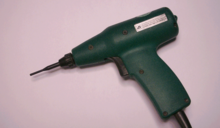
Modern wire wrapping technology was developed after WWII at Bell Laboratories as a means of making electrical connections in a new relay being designed for use in the Bell Telephone system.[1] A design team headed by Arthur C. Keller developed the “Keller Wrap Gun”, and the entire wrap system was passed over to Western Electric for industrial application. After a “make or buy” committee at Western Electric decided to have the hand tool manufactured by an outside vendor, Western Electric sent the tool contract out for bids. Keller Tool of Grand Haven, Michigan, a supplier of rotary hand tools to Western Electric, won the contract and made several design changes to make the tool easier to manufacture and to use. Keller began manufacturing the tools in 1953, and subsequently obtained a license from Western Electric allowing sale of the technology on the open market. The tool was marketed under its original name – since the name of the manufacturer was coincidentally the same as the name of the inventor.
IBM's first transistorized computers, introduced within the late 1950s, were built with the IBM Standard Modular System that used wire-wrapped backplanes.
Wire-wrap was used by Apple Computer to make early prototypes of the original Macintosh computer (The Macintosh 128K).[2]
Method
[edit]
A correctly made wire-wrap connection for 30 or 28 AWG wire is seven turns (fewer for larger wire) of bare wire with half to one and a half turns of insulated wire at the bottom for strain relief.[3][4] The square hard-gold-plated post thus forms 28 redundant contacts. The silver-plated wire coating cold-welds to the gold. If corrosion occurs, it occurs on the outside of the wire, not on the gas-tight contact where oxygen cannot penetrate to form oxides. A correctly designed wire-wrap tool applies up to twenty tons of force per square inch on each joint.
The electronic parts sometimes plug into sockets. The sockets are attached with cyanoacrylate (or silicone adhesive) to thin plates of glass-fiber-reinforced epoxy (fiberglass).
The sockets have square posts. The usual posts are 0.025 in (0.64 mm) square, 1 in (25.4 mm) high, and spaced at 0.1 in (2.54 mm) intervals. Premium posts are hard-drawn beryllium copper alloy plated with a 0.000025 in (630 nm) of gold to prevent corrosion. Less-expensive posts are bronze with tin plating.
30 gauge (~0.0509mm2) silver-plated soft copper wire is insulated with a fluorocarbon that does not emit dangerous gases when heated. The most common insulation is "Kynar". The 30 AWG Kynar wire is cut into standard lengths, then one inch of insulation is removed on each end.
There are three ways of placing wires on a board. In professionally built wire-wrap boards, long wires are placed first so that shorter wires mechanically secure the long wires. Also, to make an assembly more repairable, wires are applied in layers. The ends of each wire are always at the same height on the post, so that at most three wires need to be replaced to replace a wire. Also, to make the layers easier to see, they are made with different colors of insulation. In space-rated or airworthy wire-wrap assemblies, the wires are boxed, and may be conformally coated with wax to reduce vibration. Epoxy is never used for the coating because it makes an assembly unrepairable.[citation needed]
Tooling
[edit]

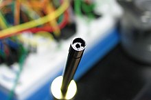
A "wire wrap tool" has two holes. The wire and 1⁄4 in (6.4 mm) of insulated wire are placed in a hole near the edge of the tool. The hole in the center of the tool is placed over the post.
The tool is rapidly twisted. The result is that 1.5 to 2 turns of insulated wire are wrapped around the post, and above that, 7 to 9 turns of bare wire are wrapped around the post. The post has room for three such connections, although usually only one or two are needed. This facilitates manual wire-wrapping to be employed for modifications or repairs.
The turn and a half of insulated wire helps prevent wire fatigue where it meets the post.
Above the turn of insulated wire, the bare wire wraps around the post. The corners of the post bite in with pressures of tons per square inch. This forces all the gases out of the area between the wire's silver plate and the post's gold or tin corners. Further, with 28 such connections (seven turns on a four-cornered post), a very reliable connection exists between the wire and the post. Furthermore, the corners of the posts are quite "sharp": they have a quite-small radius of curvature.[citation needed]
Automation
[edit]This section needs additional citations for verification. (April 2011) |

Automated wire-wrap machines, as manufactured by the Gardner Denver Company in the 1960s and 1970s, were capable of automatically routing, cutting, stripping and wrapping wires onto an electronic "backplane" or "circuit board". The machines were driven by wiring instructions encoded onto punched cards,[5] Mylar punched hole tape, and early micro computers.
The earliest machines (14FB and 14FG models, for example) were initially configured as "horizontal", which meant that the wire wrap board was placed upside down (pins up) onto a horizontal tooling plate, which was then rolled into the machine and locked onto a rotating (TRP table rotational position of four positions) and shifting (PLP = pallet longitudinal position of 11 positions) pallet assembly. These machines included very large hydraulic units for powering the servos that drove the ball screw mounted "A" and "B" drive carriages, a 6 ft (1.8 m) tall electronics cabinet loaded with hundreds of IBM control relays, many dozens of solenoids for controlling the various pneumatic mechanical subsystems, and an IBM 029 card reader for positioning instructions. The automatic wire wrap machines themselves were quite large, 6 ft (1.8 m) tall and 8 ft (2.4 m) square. Servicing the machines was extremely complex, and often meant climbing inside them just to work on them. This could be quite dangerous if safety interlocks were not maintained properly.
Later, somewhat smaller machines were "vertical" (14FV) which meant the boards were placed onto a tooling plate with pins facing the machine operator. Gone were the hydraulic units, in favor of direct drive motors to rotate the ball screws, with rotary encoders to provide positioning feedback. This generally provided better visibility of the product for the operator, although maximum wrap area was significantly less than the horizontal machines. Top speeds on horizontal machines were generally around 500-600 wires per hour, while the vertical machines could reach rates as high as 1200 per hour, depending on board quality and wiring configurations.
Considerations
[edit]Wire-wrap works well with digital circuits with few discrete components, but is less convenient for analog systems with many discrete resistors, capacitors or other components (such elements can be soldered to a header and plugged into a wire wrap socket).[6] The sockets are an additional cost compared to directly inserting integrated circuits into a printed circuit board, and add size and mass to a system. Multiple strands of wire may introduce cross-talk between circuits, of little consequence for digital circuits but a limitation for analog systems. The interconnected wires can radiate electromagnetic interference and have less predictable impedance than a printed circuit board. Wire-wrap construction cannot provide the ground planes and power distribution planes possible with multilayer printed circuit boards, increasing the possibility of noise.[7]
See also
[edit]References
[edit]- ^ Bell Telephone Laboratories (1953). "A New Twist in Telephony (advertisement)". Retrieved November 3, 2018.
- ^ "Hello. The Apple Mac @ 40". CHM. Archived from the original on January 22, 2024. Retrieved 2024-01-24.
- ^ "Standards for Discrete Wiring", Workmanship, USA: NASA, 2000-03-31, retrieved 2011-08-21
- ^ Department of Defense (12 December 1978). "Military Standard: Connections, Electrical, Solderless Wrapped" (pdf). sec. 5.3.2. Retrieved 2016-11-04.
- ^ "Computer for Apollo". MIT Science Reporter. 1965. WGBH.
- ^ Horowitz and Hill, "The Art of Electronics 3rd Edition", pp. 828-830
- ^ Horowitz and Hill "the Art of Electronics 3rd Edition", p. 816
External links
[edit]- [1] Punched card used to control an electropneumatic wire wrap machine.
- [2] Burroughs Corporation promotional video showing a wire wrap machine at 09:50.
- [3] Descriptive manual for the above machine, manufactured by Gardner Denver.
